—-
User Tools
Sidebar
This is an old revision of the document!
Table of Contents
Examples
So, as with the particles, let’s doodle up some examples to get you going.
The biggest difference when it comes to placing light emitters is that there is no default emitter set for lights, because it simply makes no sense to have one. So you can only insert single emitters with INSERT.
All the attach stuff etc is exactly the same though.
But, in case you are not interested in particles and jump straight to the lights I’ll make the examples as if you had not read any of the particle examples.
Simple
Let’s start from blank slate, press New Scenario.
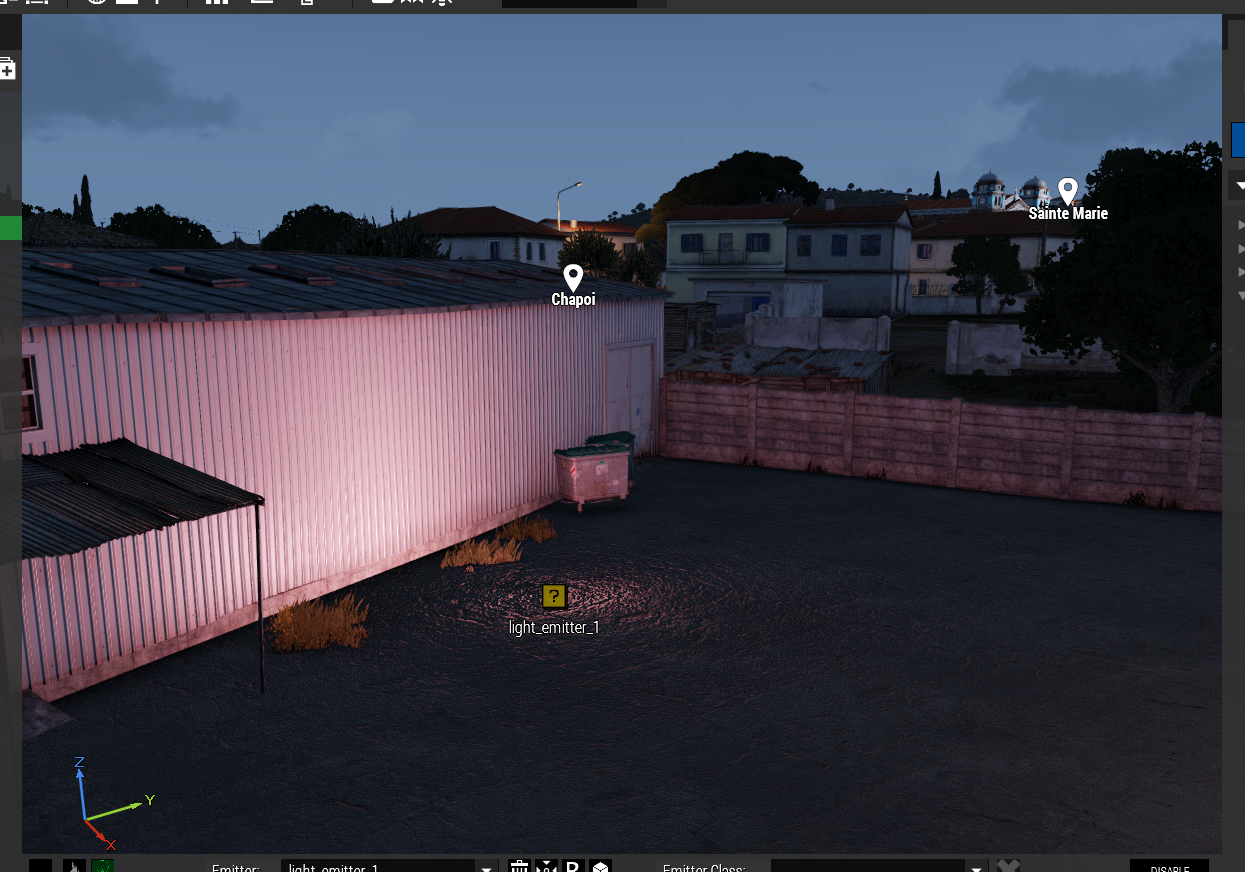
Place down a light emitter and adjust the time of day to be darker so you can actually see the light shinning.
Set the Intensity parameter to 10000. You need to use quite high values in this.
It’s not stated anywhere but the value probably is in candelas.
Set some color for the light. You can see that light color has no alpha so it’s just plain old RGB. You can also see the color change in real time when you move the sliders. And that’s it, you have a light emitter in your scenario.
Light Classes
You can also select a light class from the Emitter class list.
The classes are read from CfgLights so if you’re using a mod that has it’s own lights it is possible those are listed in the list as well. The classes in the list include only the lights that have params that can be set with the setLightXXX scripting commands, refer to the Technical issues/limitations/other notes article for details.
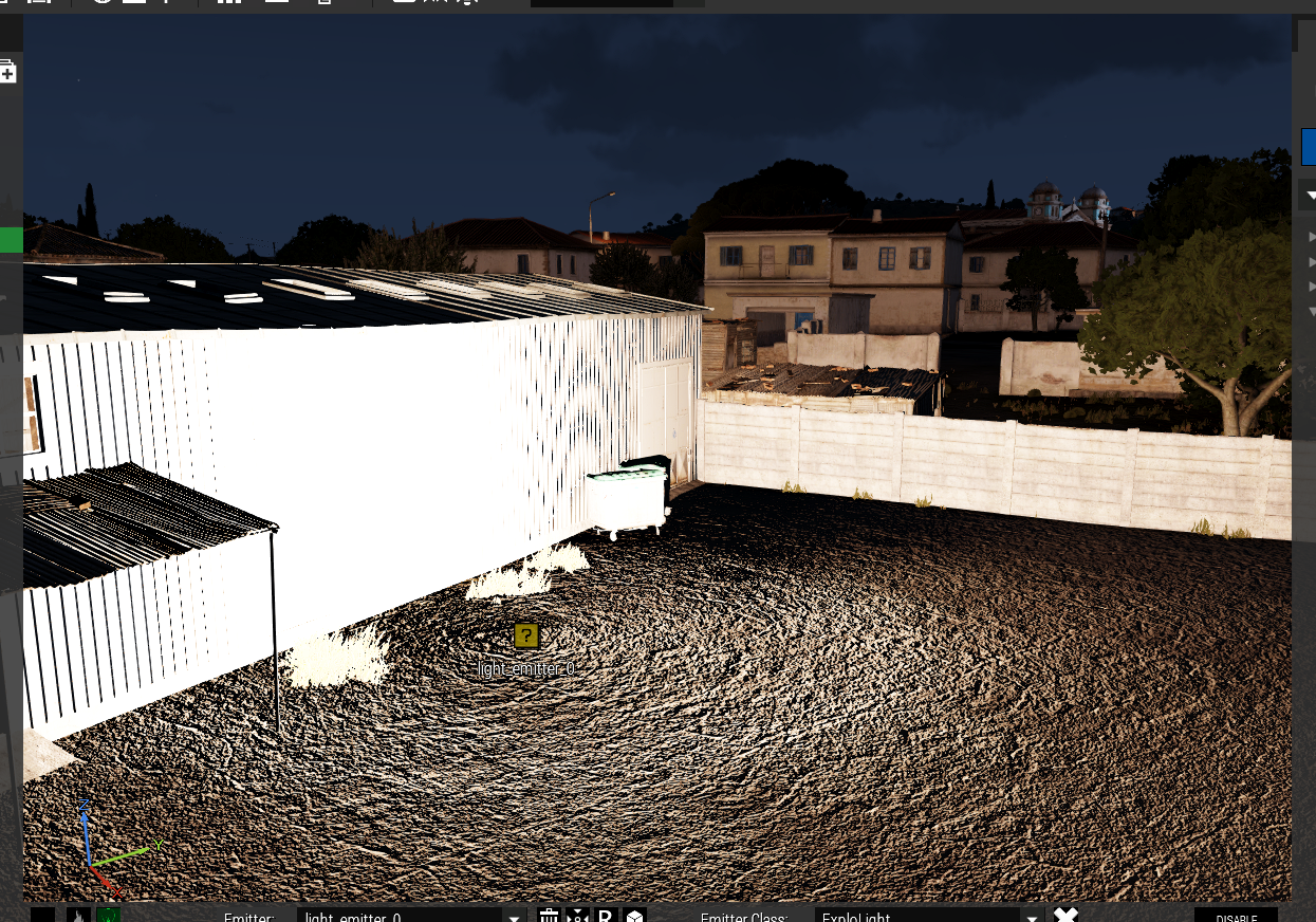
So, anyway, let’s select the class ExploLight.
Now your emitter is emitting a very bright light, which assuming from the name is flashed when something explodes.
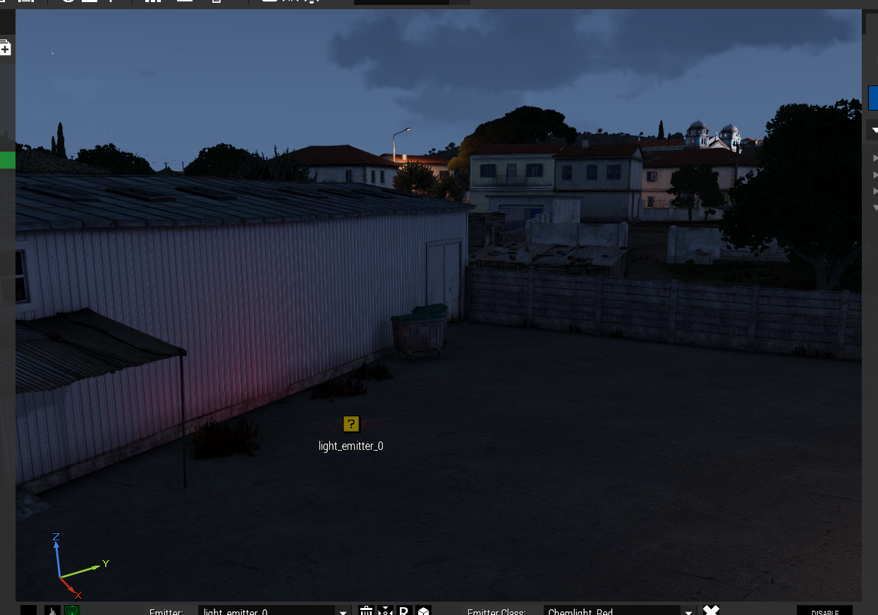
Or you can select something like Chemlight_Red, which is of course the light from the red colored Chemlight.
UFO
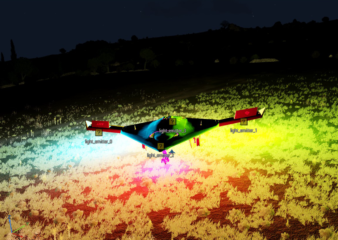
Clear the scenario, place down a big drone plane (I’m using the Sentinel in this example). Change the daytime so that it becomes dark.
Place down a light emitter and select the class Chemlight_Red, change the Intensity from 4000 to 400000 (add two zeros at the end) and Attenuation Start to 2.
IMPORTANT NOTE:
When you change the intensity param you can see how shortly after the parameter field changes color to yellow. This means the input is being validated and only after the field turns back to white is the input validated successfully and applied to the emitter. In case of faulty input you get a red Eden notification, the field turns red for about 3 seconds and then the field gets applied with either the default datatype for that field or the last known validated input.
You have to wait for the validation to finish until you can change a value in any other param field.
This makes things a bit slow but if there wasn’t such a validation faulty data could be “injected” into the emitter causing errors which in turn would cause tool’s database corruption which would mean the scenario would most likely be FUBAR…
You can also change parameter data with the mouse scroll wheel, see details in Inserting data into data fields.
Select Global attach from the attach mode selector, the button on the top menu with the “box” image on it.
Either click the button or tap SHIFT + A until it changes from ![]() to
to ![]()
Select the emitter you placed, move the mouse cursor to an empty area and press ALT + A to activate the Global attach mode. The mode is indicated by a globe symbol above the navigation widget. You will also hear a sound play and see the emitter move to the camera view center.
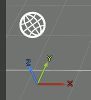
Do NOT press left mouse button, instead press and hold down the right mouse button and move the mouse around. You will notice how the emitter follows the camera view center. This is how you can position the emitter anywhere on the drone model.
Note that when the emitter is above an object surface a green reticule icon will appear over it:
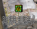
Press left mouse button to confirm attach.
Global Attach can be a tad annoying to use because the object surface detection is checked from many directions so which ever, the cursor or the emitter itself, collides with the surface there’s the surface position so the emitters may behave “oddly” and jump of to surfaces not even near the cursor. That is a feature, not a bug.
So, move the emitter to either wing, about half way and press left mouse button. You will hear a sound play and the globe symbol disappear from the screen. The attach mode selector button also turns back to the “box” image.
Then you can fine tune the emitter position by selecting the emitter, activating the Eden Translation widget and holding down CTRL on the keyboard. A green reticule will appear to indicate the emitter is movable and you can then move it with the translation widget so that the light appear under the wing/drone (keep CTRL down while “translating”).

You can also, instead of Global attach, just drag the emitter onto the entity and press SHIFT + ALT + A, this will attach the emitter to the spot it is at on the model. Requires the Eden Surface snapping switched on. The same green reticule icon will show up if the emitter is on the object surface.
Place down another light emitter, or clone the previous one with the clone button or the SHIFT + CTRL + C kb shortcut. Select the class Chemlight_Red, change the Intensity from 4000 to 40000 and Attenuation Start to 2. Select Global attach mode and move the emitter to the opposite wing from the previous emitter. Fine tune the positioning as described earlier.
Place down a third light emitter (or clone previous) and select the class Chemlight_Blue, change the Intensity from 4000 to 40000 and Attenuation Start to 2. Select Global attach mode and move the emitter somewhere to the rear of the drone and fine tune the positioning as described earlier.
Place down a fourth light emitter (or clone previous) and select the class Chemlight_Green, change the Intensity from 4000 to 40000 and Attenuation Start to 2. Select Global attach mode and move the emitter to the nose of the drone and fine tune the positioning as described earlier.
So now your drone should look like something like this:
